
Balancing excavation volumes is one of the most critical — and most overlooked — skills in civil engineering and construction. Whether you’re grading a highway, designing a subdivision, or preparing a building pad, the ability to match cut volumes with fill volumes can mean the difference between a project that stays on budget and one that bleeds money on hauling and disposal costs.
In this comprehensive guide, we’ll walk you through everything you need to know about cut and fill earthwork: what it is, why balancing matters, how professionals calculate it, and the tools and techniques you can use to optimize your own projects.
1. What Is Cut and Fill Earthwork?
Cut and fill (also known as cut-and-fill grading or stripping and grading) is the earthmoving process used to reshape a terrain to a desired elevation. It involves two complementary operations:
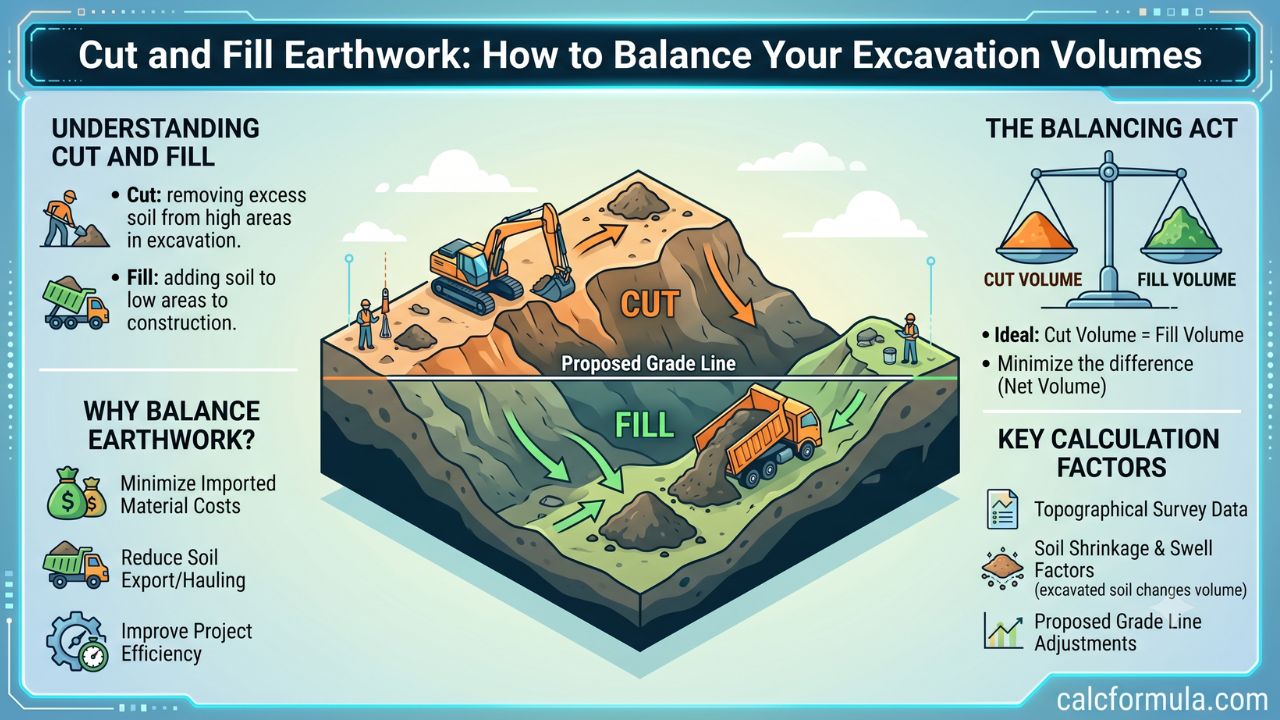
- Cut (Excavation): Removing earth from high areas (hills, ridges, humps) where the existing ground is above the proposed design grade.
- Fill (Embankment): Placing that excavated material into low areas (valleys, depressions) where the existing ground is below the proposed design grade.
When perfectly balanced, the material cut from high spots is transported directly to fill the low spots — eliminating the need to import borrow material or export surplus soil. This is the ideal scenario every earthwork engineer aims for.
Cut and fill is used across a wide range of construction applications, including:
- Road and highway construction — smoothing grade lines to reduce steep gradients
- Residential and commercial site development — creating flat building pads from sloping terrain
- Railway construction — maintaining consistent gradients across undulating landscapes
- Airport runways — achieving precise flat grades over large areas
- Golf courses and sports fields — sculpting landforms for drainage and aesthetics
- Retaining wall and terrace construction — creating level steps on hillside sites
- Mining and quarrying — managing waste material and overburden
2. Why Balancing Earthwork Volumes Matters
The financial and logistical benefits of a well-balanced earthwork plan are enormous. Here’s why it matters:
Cost Savings
Importing fill material (borrow) or exporting surplus cut material (waste) involves truck haulage, tipping fees, fuel, labor, and sometimes royalty payments. For large infrastructure projects, these costs can run into hundreds of thousands — or even millions — of dollars. A balanced site uses what’s already there.
Schedule Efficiency
Hauling materials off-site or waiting for deliveries of borrow material introduces delays. A balanced plan keeps the project moving without dependency on external supply chains.
Reduced Environmental Impact
Less trucking means reduced carbon emissions, lower fuel consumption, and less disruption to surrounding communities from noise and traffic. Sites that avoid importing or exporting material also reduce land degradation at borrow pits and disposal areas.
Structural Integrity
Properly compacted fill that comes from a known on-site source can be controlled and tested more reliably than imported material of uncertain quality. Good earthwork balance also ensures that fills are placed at the right density and moisture content.
Regulatory Compliance
Many jurisdictions require earthwork balance calculations as part of grading permits and environmental impact assessments. Demonstrating a balanced cut-and-fill design is often a permit requirement.
3. Key Terminology You Need to Know
Before diving into calculations, it helps to understand the language of earthwork:
| Term | Definition |
|---|---|
| Cut Volume | The total volume of earth removed from areas above design grade |
| Fill Volume | The total volume of earth placed in areas below design grade |
| Borrow | Material imported from an off-site source to make up a fill deficit |
| Waste (Spoil) | Surplus cut material that must be disposed of off-site |
| Swell Factor | The increase in volume that occurs when in-situ soil is excavated (loose material takes up more space than bank material) |
| Shrinkage Factor | The reduction in volume that occurs when loose fill is compacted into an embankment |
| Bank Measure (BCM) | Volume of material measured in its natural, undisturbed state |
| Loose Measure (LCM) | Volume of material measured after excavation, before compaction |
| Compacted Measure (CCM) | Volume of material after it has been compacted in place |
| Mass Haul Diagram | A graphical tool showing cumulative cut and fill volumes along a route |
| Haul Distance | The distance material must be moved from cut to fill areas |
| Free Haul | The maximum haul distance included in the unit price for earthwork |
| Overhaul | Hauling beyond the free haul limit, billed separately |
| Average Haul Distance | The weighted average distance material travels from cut to fill |
| Grading Plan | A drawing showing proposed elevations and cut/fill zones |
| Subgrade | The natural ground prepared to receive a pavement or foundation |
4. The Cut and Fill Process: Step by Step
Understanding the sequence of earthwork operations helps you plan effectively:
Step 1: Survey and Data Collection
Begin with an accurate topographic survey of the existing ground. Modern projects use:
- Total station surveys
- GPS/GNSS surveys
- LiDAR scanning (aerial or ground-based)
- Drone photogrammetry
The survey produces a digital terrain model (DTM) or digital elevation model (DEM) representing the existing ground surface.
Step 2: Design the Finished Grade
Working from the design drawings, establish the finished grade — the surface elevation the site must reach after earthworks. This could be a road alignment, a building pad level, or a complex graded surface.
Step 3: Calculate Cut and Fill Volumes
Compare the existing DTM with the proposed finished grade to identify cut zones (where existing ground is high) and fill zones (where existing ground is low). Calculate the volume of material in each zone using one of the calculation methods described in Section 5.
Step 4: Apply Swell and Shrinkage Factors
Raw cut volumes must be adjusted for swell and shrinkage (see Section 8) to determine how much compacted fill a given volume of cut will actually produce.
Step 5: Perform Mass Haul Analysis
Plot the cumulative earthwork diagram to identify the most efficient way to move material from cut areas to fill areas. Optimize haul distances to minimize cost.
Step 6: Identify Borrow or Waste Requirements
If the adjusted fill volume exceeds available cut, calculate how much borrow material you’ll need. If cut exceeds fill, calculate the surplus that must be wasted.
Step 7: Develop an Earthwork Management Plan
Schedule earthwork operations, identify haul routes, specify equipment requirements, and plan for material stockpiling and management.
Step 8: Execute and Monitor
During construction, monitor actual volumes against estimates. Use GPS machine guidance, compaction testing, and survey checks to ensure the plan is being executed accurately.
5. Methods for Calculating Cut and Fill Volumes
Accurate volume calculation is the foundation of earthwork balance. Several methods exist, each suited to different situations:
5.1 Average End Area Method
The most widely used method for linear projects like roads and railways. It calculates the volume between two cross-sections by averaging their areas and multiplying by the distance between them:
V = L × (A₁ + A₂) / 2
Where:
- V = Volume between two sections (m³ or yd³)
- L = Distance between sections
- A₁, A₂ = Cross-sectional areas of cut or fill at each section
This method is simple and conservative but can overestimate volumes when cross-section areas change significantly.
5.2 Prismoidal Formula
More accurate than the average end area method, particularly when sections vary significantly. It adds a middle area calculation:
V = L × (A₁ + 4Am + A₂) / 6
Where Am is the cross-sectional area at the midpoint. The prismoidal formula is the preferred method when higher accuracy is required.
5.3 Grid (Borrow Pit) Method
Used for calculating volumes over irregular areas — like site pads, ponds, or borrow pits. The site is divided into a grid of squares or rectangles. Cut or fill depths are measured at each grid intersection and averaged over each cell:
V = Grid Area × Average Depth
Summing all grid cells gives the total volume. Grid size is typically 5m × 5m to 20m × 20m depending on the complexity of the terrain.
5.4 Contour Method
Based on planimetric areas enclosed by contour lines on a topographic map. The volume between two contours is:
V = (h/2) × (A₁ + A₂)
Where h is the contour interval and A₁, A₂ are the areas enclosed by adjacent contours. This method works well for reservoir or stockpile volume calculations.
5.5 Triangulated Irregular Network (TIN) Method
Modern software uses TIN models — a mesh of triangles connecting survey points — to calculate volumes between two surfaces with high precision. This is the standard approach in civil design software like AutoCAD Civil 3D, Bentley OpenRoads, and Trimble Business Center.
5.6 Online Calculator Method
For quick estimates, online tools offer immediate results without specialist software. The Cut and Fill Calculator at CalcFormula.com provides fast, accurate volume estimates based on your site dimensions and grade changes — ideal for preliminary planning, feasibility studies, or checking your manual calculations.
6. How to Balance Your Earthwork Volumes
Achieving earthwork balance is as much an art as a science. Here are the strategies professionals use:
6.1 Adjust the Design Grade
The most direct way to balance cut and fill is to raise or lower the finished grade elevation. If you have more cut than fill, lowering the grade increases fill and decreases cut. Raising it has the opposite effect.
For a road design, this means adjusting the vertical alignment. For a site pad, it means shifting the proposed platform elevation. Even small adjustments of a few hundred millimetres can significantly shift the balance.
6.2 Shift the Horizontal Alignment
For road and railway projects, shifting the horizontal alignment laterally moves cross-sections into different terrain, changing the balance of cut and fill along the route. The horizontal and vertical alignments are often optimized together to find the best overall balance.
6.3 Change Slope Gradients
Adjusting cut slope angles and fill slope angles changes the volume of material involved. Steeper cut slopes reduce the cut volume; flatter fill slopes require more fill material. However, slope angles must always satisfy stability requirements — see Section 9 below.
6.4 Relocate Fill Areas
Sometimes it’s possible to use cut material to create features like berms, mounds, or noise embankments elsewhere on-site, consuming surplus material that would otherwise need to be wasted.
6.5 Stage the Earthworks
For large sites, phasing the earthworks so that material from early excavations is stockpiled and later used as fill in subsequent phases can help achieve balance across the total project.
6.6 Apply Correct Volume Conversion Factors
Ensuring that you’re converting bank cubic metres to compacted cubic metres correctly (using site-specific swell and shrinkage factors) is essential to achieving true balance. See Section 8 for details.
6.7 Use a Cut and Fill Calculator
Tools like the Cut and Fill Calculator allow you to quickly iterate through different design scenarios — adjusting grades, dimensions, and slopes — to see how each change affects the volume balance. This makes the optimization process much faster than manual calculation.
7. Mass Haul Analysis and the Mass Haul Diagram
For linear projects, the mass haul diagram is the definitive tool for earthwork optimization.
What Is a Mass Haul Diagram?
A mass haul diagram (also called a mass ordinate diagram or Brückner diagram) is a graph that plots cumulative earthwork volume against distance along a route. It shows:
- Where cuts and fills occur along the alignment
- How much material is available at each point
- The most economical direction to haul material
- Where borrow or waste areas will be needed
How to Read a Mass Haul Diagram
- Rising portions of the curve represent cut zones (material being excavated)
- Falling portions represent fill zones (material being placed)
- Peaks are transitions from cut to fill
- Valleys are transitions from fill to cut
A horizontal line (called a balance line) intersects the curve at points where the total volume of cut and fill are equal. The horizontal distance between two intersection points represents the haul length for a given volume of material.
Using the Mass Haul Diagram to Minimize Costs
The goal is to draw balance lines that:
- Keep haul distances within the free haul limit wherever possible
- Minimize the total overhaul (mass × distance)
- Position borrow and waste areas at the ends of the alignment where material deficit or surplus exists
For complex projects, software algorithms optimize the mass haul automatically, finding the lowest-cost earthwork distribution plan.
8. Swell and Shrinkage Factors
One of the biggest sources of error in earthwork calculations is failure to apply swell and shrinkage factors correctly.
What Is Swell?
When soil is excavated from its natural (bank) state, the particles are loosened and the material expands. This is called swell. A cubic metre of bank material becomes more than a cubic metre when loosened for haulage.
Swell percentage varies by material type:
| Material | Swell Factor | Approximate % Swell |
|---|---|---|
| Sandy loam | 1.10–1.15 | 10–15% |
| Clay | 1.20–1.35 | 20–35% |
| Dense gravel | 1.05–1.15 | 5–15% |
| Soft rock | 1.30–1.50 | 30–50% |
| Hard rock | 1.50–1.80 | 50–80% |
What Is Shrinkage?
When loose fill material is compacted into an embankment, its volume is reduced below that of the bank material. This is shrinkage. One bank cubic metre of material typically compacts to 0.80–0.95 compacted cubic metres.
Load factor (LF) converts loose volume to bank volume: Bank Volume = Loose Volume × Load Factor
Compaction factor (CF) converts bank volume to compacted volume: Compacted Volume = Bank Volume × Compaction Factor
Practical Example
If you excavate 1,000 bank cubic metres (BCM) of clay (swell factor = 1.25, shrinkage factor = 0.88):
- Loose volume on trucks = 1,000 × 1.25 = 1,250 LCM
- Compacted fill volume = 1,000 × 0.88 = 880 CCM
This means 1,000 BCM of excavated clay only provides 880 CCM of compacted fill. To fill a 1,000 CCM void, you’d need 1,000 / 0.88 = 1,136 BCM of cut material.
Always obtain swell and shrinkage factors from laboratory testing or site trial fills for accurate earthwork balance.
9. Excavation Slopes and Stability
Slope design is an inseparable part of earthwork planning. Getting it wrong can cause slope failures that endanger workers, damage property, and invalidate your volume calculations.
Why Slope Angles Matter for Volume Balance
The angle of cut and fill slopes directly affects the volume of earth involved:
- A flatter cut slope (e.g., 1V:3H) intercepts more earth than a steeper cut slope (e.g., 1V:1H), producing a larger cut volume
- A steeper fill slope requires less fill material than a flatter fill slope
Adjusting slope ratios is therefore a tool for fine-tuning earthwork balance — but it must always be done within safe limits.
Factors Affecting Safe Slope Design
The maximum safe slope angle depends on:
- Soil type and classification (cohesive vs. granular, rock vs. soil)
- Soil strength parameters (cohesion c, internal friction angle φ)
- Groundwater conditions (saturated slopes fail more easily)
- Height of the slope (taller cuts require flatter slopes)
- Seismic loading (in earthquake zones)
- Surcharge loads (equipment, stockpiles near the edge)
- Time of exposure (temporary vs. permanent slopes)
Typical Safe Slope Ratios
| Material | Temporary Slope | Permanent Slope |
|---|---|---|
| Firm cohesive soil (stiff clay) | 1V:1H | 1V:1.5H |
| Loose cohesive soil (soft clay) | 1V:2H | 1V:3H |
| Sandy/granular soil | 1V:1.5H | 1V:2H |
| Gravel | 1V:1H | 1V:1.5H |
| Soft rock | 1V:0.5H | 1V:1H |
| Hard rock | 1V:0.25H | 1V:0.5H |
Always consult a geotechnical engineer for permanent slope designs and for any excavation deeper than 1.5 metres in cohesive soil or 1.2 metres in granular soil.
Using an Excavation Slope Calculator
Manually computing the geometry and volume of sloped excavations — including benching, battering, and setback distances — can be complex and error-prone. The Excavation Slope Calculator at CalcFormula.com simplifies this process, helping you determine the correct batter angles, setback widths, and volumes based on your soil type and excavation depth. It’s an invaluable tool for site planners and safety officers who need quick, reliable results.
10. Common Challenges and How to Overcome Them
Even well-designed earthwork plans encounter problems. Here are the most common challenges and practical solutions:
Challenge 1: Poor Soil Investigation Data
Problem: Inaccurate geotechnical data leads to wrong swell/shrinkage factors, unexpected rock, or unsuitable fill material.
Solution: Invest in adequate soil investigation before design. For large sites, a grid of trial pits and boreholes at 20–50m spacing provides enough data for reliable volume estimates and material classification.
Challenge 2: Unexpected Groundwater
Problem: Groundwater makes excavation unstable and fill placement difficult, and may require dewatering that adds cost and delays.
Solution: Include groundwater investigation in the geotechnical program. Design dewatering systems and include provisional sums for dewatering in the budget.
Challenge 3: Unsuitable Material
Problem: Some excavated material is too wet, too compressible, or contaminated to use as structural fill, requiring disposal.
Solution: Account for unsuitable material in your earthwork balance by calculating a “waste” volume and sourcing replacement borrow material. Testing fill material acceptance criteria (Atterberg limits, moisture content, CBR) before placement avoids costly rework.
Challenge 4: Seasonal Conditions
Problem: Wet weather turns otherwise acceptable material into unworkable mud. Dry conditions cause excessive dust and may require water for compaction.
Solution: Plan earthwork schedules to avoid the wettest months where possible. Include provisions for drying areas (aeration zones) and moisture conditioning of fill material.
Challenge 5: Volume Estimation Errors
Problem: Manual calculations using simplified methods (average end area) may over- or under-estimate volumes, leading to budget surprises.
Solution: Use more accurate methods (prismoidal formula, TIN modeling, grid method) for complex terrain. Cross-check estimates using online tools like the Cut and Fill Calculator to validate your numbers before committing to a contract.
Challenge 6: Design Changes During Construction
Problem: Late design changes alter grades and alignments, disrupting the earthwork balance and requiring additional borrow or creating surplus.
Solution: Freeze design decisions before earthworks begin wherever possible. Establish a formal change management process that includes earthwork impact assessment for any proposed design change.
11. Cost Implications of Poor Earthwork Balance
Let’s quantify the financial stakes with a worked example.
Scenario: A residential subdivision site requiring 10,000 m³ of grading.
| Scenario | Description | Approximate Cost |
|---|---|---|
| Balanced | All cut material used as fill on-site | Base cost only |
| 5% deficit | 500 m³ of borrow needed at $25/m³ | +$12,500 |
| 10% deficit | 1,000 m³ of borrow needed at $25/m³ | +$25,000 |
| 10% surplus | 1,000 m³ of waste disposal at $20/m³ | +$20,000 |
| Unbalanced | 15% deficit + 10% waste | +$50,000+ |
For larger infrastructure projects (roads, highways, reservoirs), where earthwork volumes can run into millions of cubic metres, the cost of poor balance multiplies dramatically. A 5% imbalance on a 5-million-m³ project could mean $2.5–5 million in unexpected costs.
Beyond direct earthwork costs, poor balance also drives up:
- Haul road maintenance costs from increased truck movements
- Equipment wear and fuel from longer haul distances
- Project management costs from rescheduling and change orders
- Environmental compliance costs if unauthorized disposal or borrowing occurs
This is why upfront investment in accurate earthwork calculation — using the right tools, methods, and professional expertise — pays for itself many times over.
12. Environmental Considerations
Responsible earthwork management goes beyond cost. Modern construction must account for environmental impacts:
Erosion and Sediment Control
Freshly graded surfaces are highly susceptible to erosion. An Erosion and Sediment Control Plan (ESCP) should be developed before earthworks start, including:
- Silt fences and sediment basins at drainage outlets
- Stabilization of temporary cut and fill slopes with erosion matting or hydromulch
- Staged earthworks to minimize exposed area at any one time
- Prompt revegetation or paving of finished surfaces
Topsoil Management
The top 150–300mm of soil contains the biological activity and nutrients needed for revegetation. Strip and stockpile topsoil separately before main earthworks begin. Re-spread topsoil over finished surfaces to promote healthy vegetation establishment.
Acid Sulfate Soils
In coastal and wetland areas, excavating below the water table can expose acid sulfate soils, which oxidize on contact with air and release sulfuric acid — devastating to waterways and structures. Always test for acid sulfate soils before excavation and follow management plans if present.
Contaminated Land
On brownfield sites, excavation may disturb contaminated material. Identify contamination risks through Phase 1 and Phase 2 environmental assessments, and include contaminated material management in your earthwork plan.
Vegetation and Habitat
Clear only the area needed for construction. Retain mature trees and significant vegetation wherever possible. Protect root zones during earthworks and avoid stockpiling material over tree roots.
13. Software and Online Tools
Modern earthwork professionals have access to a wide range of tools, from sophisticated design software to practical online calculators.
Professional Civil Design Software
- AutoCAD Civil 3D — Industry-standard for road and site earthwork design, TIN surface modeling, and mass haul analysis
- Bentley OpenRoads — Comprehensive design tool for transportation infrastructure
- 12d Model — Popular in Australia and the UK for civil design and earthworks
- Trimble Business Center — Data processing and volume calculation from survey instruments
- Carlson Civil — AutoCAD-based civil design with strong earthwork tools
Specialist Earthwork Software
- AGTEK EarthWorks — Estimating software for earthmoving contractors
- HCSS HeavyBid — Construction cost estimating with earthwork modules
- B2W Software — Field tracking and optimization for earthwork operations
Online Calculators for Quick Estimates
For preliminary planning, quick checks, and situations where full design software isn’t available, online calculators are fast and accessible:
Cut and Fill Calculator — The CalcFormula Cut and Fill Calculator lets you quickly compute earthwork volumes, balance cut against fill, and estimate borrow or waste quantities. Perfect for feasibility studies, budget estimates, and checking your manual calculations.
Excavation Slope Calculator — The CalcFormula Excavation Slope Calculator helps you determine the correct batter ratios, setback widths, and excavation volumes for sloped cuts. Input your depth, soil type, and slope ratio to get instant results — a practical tool for site managers, safety officers, and estimators.
These free tools are accessible from any device and require no software installation, making them ideal for field use and quick design iterations.
14. Frequently Asked Questions
What is the difference between cut and fill in civil engineering?
In civil engineering, “cut” refers to the excavation of earth from areas that are higher than the proposed design grade, while “fill” refers to placing earth material into areas that are lower than the proposed design grade. The two operations work together to reshape terrain to a desired elevation profile.
How do you calculate cut and fill volumes?
The most common method is the average end area method, which averages the cross-sectional areas at two stations and multiplies by the distance between them: V = L × (A₁ + A₂) / 2. The more accurate prismoidal formula adds a mid-section: V = L × (A₁ + 4Am + A₂) / 6. For site plans, the grid method divides the area into cells and sums volume contributions from each cell. You can also use the Cut and Fill Calculator for fast, reliable results.
What does it mean to balance earthwork?
Balancing earthwork means equalizing the volume of cut material with the volume needed for fill, so that no borrow material needs to be imported and no surplus material needs to be exported. A perfectly balanced site uses all of its excavated material as fill on-site, minimizing cost and environmental impact.
What is the swell factor in earthworks?
The swell factor accounts for the expansion that occurs when in-situ soil is excavated. When soil is dug up, it loosens and occupies a greater volume than it did in the ground. Swell percentages typically range from 10–15% for sandy soils to 50–80% for hard rock. Applying the correct swell factor is essential for accurate volume balance.
Why is slope angle important in excavation?
Slope angle determines the stability of cut and fill faces. Too steep an angle causes slope failure, which can injure workers and damage property. Too flat an angle increases the volume of earth that must be moved. The correct slope angle depends on soil type, groundwater conditions, slope height, and whether the excavation is temporary or permanent. Use the Excavation Slope Calculator to calculate safe batter ratios for your specific conditions.
What is a mass haul diagram?
A mass haul diagram is a graphical representation of cumulative earthwork volumes along a linear project. It shows how cut and fill zones relate to each other, helping planners determine the most economical way to move material from cuts to fills, and identifying where borrow or waste areas will be required.
How much does earthwork cost per cubic meter?
Earthwork costs vary widely based on location, material type, haul distance, and site conditions. Typical ranges (indicative only):
- General excavation: $8–25/m³
- Borrow material delivered: $15–40/m³
- Waste disposal: $10–30/m³
- Rock excavation: $30–150/m³
Balancing earthwork on-site can eliminate borrow and waste costs entirely, potentially saving tens or hundreds of thousands of dollars.
Conclusion
Balancing cut and fill earthwork volumes is not just a technical exercise — it is a fundamental driver of project cost, schedule, and environmental performance. The best earthwork designs use the natural terrain to their advantage, moving material efficiently from areas of surplus to areas of need, minimizing the distance material travels and eliminating the need for off-site borrow or disposal.
Getting the balance right requires:
- Accurate topographic survey data as the foundation
- Correct swell and shrinkage factors based on site testing
- Sound calculation methods appropriate to the project type and terrain
- Iterative design refinement adjusting grades, alignments, and slopes until balance is achieved
- Mass haul analysis to optimize material distribution and minimize haulage costs
- Good slope design that is safe, stable, and integrated with the volume balance
Whether you’re a civil engineer working on a major infrastructure project, a contractor estimating earthworks for a site development, or a project manager trying to understand where your budget is going, the principles in this guide will help you make better decisions about earthwork planning and management.
Start your next project with the right tools. Use the Cut and Fill Calculator for fast volume estimates, and the Excavation Slope Calculator to ensure your cut and fill slopes are safe and correctly proportioned. Together, these tools give you the confidence to plan, price, and execute earthwork operations accurately.