
By a Licensed Structural Engineer, PE | Updated June 2026
When a beam carries a load, it doesn’t just deflect — it develops internal stresses that can cause failure if they exceed the material’s capacity. Understanding bending stress in beams is foundational to structural engineering, mechanical design, and construction. Whether you’re sizing a floor joist, selecting a steel I-beam, or designing a shaft in a machine, the same fundamental formula governs how a beam resists bending — and whether it will hold.
This guide breaks down the flexure formula from first principles, explains every variable, walks through a complete worked example step by step, and addresses the most frequent errors engineers and students make when applying it. By the end, you’ll be able to calculate bending stress in beams confidently for any cross-section and loading condition.
Quick Answer: The Bending Stress Formula
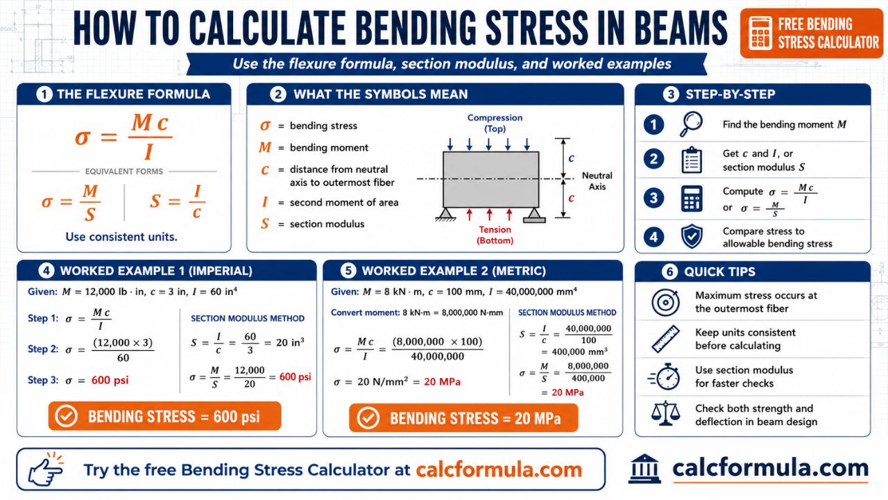
The bending stress at any point in a beam cross-section is given by the Flexure Formula:
σ = (M × c) / IWhere:
- σ = bending stress at the point of interest (Pa, MPa, or psi)
- M = bending moment at the cross-section (N·m, N·mm, or lb·in)
- c = perpendicular distance from the neutral axis to the point of interest (m, mm, or in)
- I = second moment of area (moment of inertia) of the cross-section about the neutral axis (m⁴, mm⁴, or in⁴)
To find maximum bending stress, set c equal to the distance from the neutral axis to the extreme outer fiber (the top or bottom surface of the beam). This gives the highest stress value, which is what design calculations use for safety checks.
An equivalent form using section modulus (Z) simplifies the calculation:
σ_max = M / Z where Z = I / cSection modulus Z combines I and c into a single geometric property for the cross-section — the larger the Z, the more efficiently the section resists bending. Want to skip the arithmetic and check results instantly? Use the free Bending Stress Calculator at CalcFormula.com to calculate σ, Z, and I for any cross-section in seconds.
What Affects Bending Stress in Beams?
1. Bending Moment (M)
The bending moment is the internal moment that develops inside the beam to resist the tendency of applied loads to rotate a cross-section. Its magnitude varies along the beam’s length — peaking at specific locations depending on load type and support conditions.
Common bending moment formulas:
| Loading Condition | Max Bending Moment |
|---|---|
| Simply supported, center point load P | M = PL / 4 |
| Simply supported, uniform distributed load w | M = wL² / 8 |
| Cantilever, tip point load P | M = PL |
| Cantilever, uniform distributed load w | M = wL² / 2 |
| Fixed-fixed beam, center point load P | M = PL / 8 (at midspan) |
Where L = span length and w = load per unit length. Units must be consistent throughout — if force is in Newtons and length in millimeters, moment is in N·mm.
Use the Beam Load Calculator to determine the maximum bending moment for your specific span, support type, and loading condition before plugging it into the flexure formula.
2. Second Moment of Area / Moment of Inertia (I)
The moment of inertia I describes how efficiently a cross-section’s area is distributed relative to the bending axis. Area that is far from the neutral axis contributes more to I (because the contribution scales with the square of the distance). This is why I-beams are so efficient — they concentrate material at the flanges, far from the neutral axis, maximizing I without wasting material in the web.
Common section moment of inertia formulas:
| Cross-Section | Moment of Inertia (I) about Centroidal Axis |
|---|---|
| Rectangle (b × h) | I = bh³ / 12 |
| Solid circle (diameter d) | I = πd⁴ / 64 |
| Hollow rectangle (B×H outer, b×h inner) | I = (BH³ − bh³) / 12 |
| Hollow circle (D outer, d inner) | I = π(D⁴ − d⁴) / 64 |
| Triangle (base b, height h) | I = bh³ / 36 |
For composite sections (like a T-beam or a built-up section), use the Parallel Axis Theorem:
I_total = Σ (I_centroid + A × d²)Where A is the area of each sub-region and d is the distance between that sub-region’s centroid and the total section’s neutral axis.
3. Distance from Neutral Axis to Extreme Fiber (c)
The neutral axis is the line within the cross-section where bending stress equals zero. For symmetric cross-sections (rectangles, circles, standard I-beams), the neutral axis passes through the geometric centroid. For asymmetric sections (T-beams, L-sections, channels), the neutral axis must be located by finding the true centroid.
For maximum bending stress, c is taken as the maximum distance from the neutral axis to the extreme tension or compression fiber:
- Rectangular section (height h): c = h/2
- Solid circular section (diameter d): c = d/2
- T-section: c is different for the top and bottom fiber — calculate both if material tensile and compressive strengths differ (critical for concrete and cast iron)
4. Section Modulus (Z)
Section modulus Z = I/c is the single most useful geometric property for beam design. It directly tells you how much bending moment a cross-section can carry before reaching a given stress level:
M_allowable = σ_allowable × ZSection modulus for common shapes:
| Cross-Section | Section Modulus (Z) |
|---|---|
| Rectangle (b × h) | Z = bh² / 6 |
| Solid circle (diameter d) | Z = πd³ / 32 |
| Hollow circle (D, d) | Z = π(D⁴ − d⁴) / (32D) |
For steel I-beams and wide-flange sections, Z (elastic section modulus, listed as S in AISC tables) is tabulated directly in steel construction manuals — no manual calculation needed. When using the Bending Stress Calculator, you can input Z directly if it’s available from a section table.
5. Material Properties: Allowable Bending Stress
The calculated bending stress σ must be compared against the material’s allowable bending stress to determine safety:
- Structural steel (A36): Allowable bending stress ≈ 165 MPa (24,000 psi) under ASD
- Douglas Fir-Larch No. 2 lumber: Reference bending stress Fb ≈ 900 psi (with size and wet-use adjustment factors)
- Aluminum 6061-T6: Allowable bending stress ≈ 150 MPa in flexure
- Concrete: Concrete doesn’t take tension well — bending stress design for concrete uses limit-state methods (ACI 318), not the elastic flexure formula directly
The factor of safety (FOS) for bending is defined as:
FOS = σ_yield / σ_calculatedA factor of safety below 1.0 means the beam will yield. Most structural designs require FOS ≥ 1.5 to 2.0 depending on application and consequence of failure.
Step-by-Step Worked Example: Calculating Bending Stress in Beams
Problem: A simply supported timber beam with a rectangular cross-section (100 mm wide × 200 mm deep) spans 4 meters. It carries a uniformly distributed load of 3 kN/m over its full length. Calculate the maximum bending stress and determine whether the beam is adequate if the allowable bending stress for the timber species is 10 MPa.
Step 1: Calculate the Maximum Bending Moment
For a simply supported beam with a uniform distributed load:
M_max = wL² / 8Where:
- w = 3 kN/m = 3,000 N/m
- L = 4 m
M_max = (3,000 N/m × 4²) / 8
M_max = (3,000 × 16) / 8
M_max = 48,000 / 8
M_max = 6,000 N·m = 6 kN·m
Step 2: Calculate the Moment of Inertia (I)
For a rectangular section (b = 100 mm, h = 200 mm):
I = bh³ / 12
I = (100 × 200³) / 12
I = (100 × 8,000,000) / 12
I = 800,000,000 / 12
I = 66.67 × 10⁶ mm⁴
Step 3: Find the Distance to the Extreme Fiber (c)
The neutral axis of a rectangle is at mid-height:
c = h / 2 = 200 / 2 = 100 mmStep 4: Apply the Flexure Formula
Convert M to consistent units (N·mm):
M = 6,000 N·m = 6,000,000 N·mmNow apply σ = Mc / I:
σ_max = (6,000,000 N·mm × 100 mm) / (66.67 × 10⁶ mm⁴)
σ_max = 600,000,000 / 66,670,000
σ_max = 9.0 MPa
Step 5: Check Against Allowable Stress
σ_calculated = 9.0 MPa
σ_allowable = 10.0 MPa
Since 9.0 MPa < 10.0 MPa, the beam is adequate — with approximately 10% stress reserve. Factor of safety = 10.0 / 9.0 = 1.11.
Note that this is a relatively thin margin. If loads increase, spans extend, or load duration factors apply (for timber design), the beam may need to be upsized to 100 mm × 225 mm or 100 mm × 250 mm.
Step 6: Verify Using Section Modulus
Cross-check using Z = I/c:
Z = 66.67 × 10⁶ mm⁴ / 100 mm = 666,700 mm³Or using the direct formula Z = bh²/6:
Z = (100 × 200²) / 6 = (100 × 40,000) / 6 = 4,000,000 / 6 = 666,667 mm³ ✓Maximum bending stress:
σ = M / Z = 6,000,000 / 666,667 = 9.0 MPa ✓Both methods agree. For complex cross-sections or quick verification of multiple beam options, the Bending Stress Calculator performs these steps instantly — useful when comparing section depths or evaluating upgrade options.
Common Mistakes When Calculating Bending Stress in Beams
Mistake 1: Mixing Units Throughout the Calculation
This is the most frequent and most costly error. Mixing meters and millimeters in the same calculation — or Newton-meters and Newton-millimeters — produces results that are off by factors of 1,000 or 1,000,000. There is no automatic unit conversion in the flexure formula.
The fix: Before writing a single number, declare your unit system (SI: N and mm; or SI: kN and m) and stick to it for every value in the calculation. Moment of inertia in mm⁴, moment in N·mm, stress in MPa (N/mm²). Alternatively, moment of inertia in m⁴, moment in N·m, stress in Pa.
Mistake 2: Using the Wrong Location for the Neutral Axis
For symmetric sections — rectangles, circles, standard I-beams — the neutral axis passes through the geometric centroid at mid-height. Students often assume this is always true and apply c = h/2 to T-beams, L-sections, or composite beams where the centroid is not at mid-height.
The fix: For any non-symmetric section, locate the centroid first using the weighted area method (Ȳ = ΣAy / ΣA), then measure c from that centroid to each extreme fiber. For asymmetric sections, the tension-side c and compression-side c will differ — calculate bending stress for both and check against the allowable for each.
Mistake 3: Applying Maximum Moment Without Drawing the Bending Moment Diagram
Simply looking up a formula for maximum bending moment works for standard load cases, but most real beams carry multiple loads, partial distributed loads, or non-standard support conditions. Applying M = PL/4 when the beam also carries a significant distributed load leads to a substantial underestimate of the true maximum moment.
The fix: Sketch the shear force diagram and bending moment diagram (SFD/BMD) for the actual loading. The peak value on the BMD is the correct M to use. The Beam Load Calculator generates SFDs and BMDs automatically for combined loading conditions, saving significant calculation time.
Mistake 4: Confusing Elastic Section Modulus (S or Z_e) and Plastic Section Modulus (Z or Z_p)
In steel design, two section modulus values exist. The elastic section modulus (called S in AISC notation, Z in many other standards) is I/c and applies to the flexure formula for stress at first yield. The plastic section modulus Z (AISC) accounts for full plastic yielding across the entire cross-section and is used for plastic moment capacity (M_p = F_y × Z). Using the plastic section modulus in the elastic flexure formula overstates section capacity under working loads.
The fix: For elastic stress calculations (the flexure formula), always use I/c. Reserve the plastic section modulus for limit-state design calculations under LRFD specifically.
Mistake 5: Forgetting to Account for Beam Self-Weight
Structural design commonly focuses on applied loads — people, equipment, snow — but the beam’s own weight is a uniformly distributed load that generates its own bending moment. For short, lightly loaded spans this is negligible. For long-span beams or heavy cross-sections, self-weight can add 5–15% to the total bending moment.
The fix: Calculate beam self-weight (unit weight × cross-section area × length), convert to a distributed load (N/m or lb/ft), and add it to the applied UDL before computing M_max.
Mistake 6: Ignoring Lateral-Torsional Buckling for Unbraced Beams
The flexure formula gives the bending stress assuming the beam’s cross-section reaches full material strength. However, long, unbraced compression flanges can buckle laterally before the extreme fiber reaches yield — a phenomenon called lateral-torsional buckling (LTB). LTB reduces the effective bending capacity below the value predicted by the flexure formula alone.
The fix: For steel beams with unbraced compression flanges longer than the limiting unbraced length (L_p in AISC), apply the appropriate LTB reduction factor before comparing against allowable stress. Timber design uses beam stability factor C_L for the same purpose.
Pro Tip: Design for Section Modulus First
Rather than trial-and-error with cross-section dimensions, rearrange the flexure formula to solve for the required section modulus directly:
Z_required = M / σ_allowableThen select a cross-section (from a steel table, timber size chart, or your own dimensions) whose Z equals or exceeds Z_required. This approach eliminates guesswork and is how professional engineers size beams efficiently.
FAQ: Bending Stress in Beams
Q1: What is bending stress in a beam and how is it different from shear stress?
Bending stress (also called flexural stress or normal stress in bending) acts perpendicular to the cross-section — it’s a tension or compression stress that develops because bending stretches the fibers on one side of the beam and compresses them on the other. Shear stress in beams acts parallel to the cross-section, resulting from the vertical shear force carried by the beam. In most beams, bending stress governs the design for long spans, while shear stress governs for short, heavily loaded spans. The flexure formula (σ = Mc/I) calculates bending stress; a separate formula (τ = VQ/It) calculates shear stress distribution.
Q2: Where does maximum bending stress occur in a beam?
Maximum bending stress always occurs at the extreme outer fibers of the cross-section — the points farthest from the neutral axis — at the location along the beam’s length where the bending moment is greatest. For a simply supported beam with a center point load, maximum bending stress is at the top and bottom surfaces of the beam at midspan. For a cantilever, it’s at the top and bottom surfaces at the fixed support.
Q3: What is the section modulus and why is it important?
Section modulus Z = I/c is a geometric property of the beam cross-section that combines moment of inertia and distance to the extreme fiber into a single value. It directly represents a cross-section’s resistance to bending: the higher the section modulus, the less bending stress results from a given moment. In practical design, Z_required = M/σ_allowable tells you the minimum section modulus needed to safely carry the design moment, making it the primary selection criterion when choosing beam sizes from standard tables.
Q4: How does the moment of inertia affect bending stress in beams?
Moment of inertia I appears in the denominator of the flexure formula (σ = Mc/I), so a larger I directly reduces bending stress for the same applied moment. This is why engineers orient beams to maximize I about the bending axis — a 2×10 lumber beam placed upright (bending about its strong axis, I = bh³/12 with large h) resists far more bending stress than the same board laid flat (small h). Similarly, I-beams are efficient because their flanges — placed far from the neutral axis — contribute h² terms to I while the web keeps the flanges connected.
Q5: How do I calculate bending stress in a T-beam or composite section?
For a T-beam or any composite section, the calculation follows the same flexure formula but requires two additional steps first: (1) locate the true centroid using weighted areas (Ȳ = ΣAᵢyᵢ / ΣAᵢ), which gives the neutral axis position; and (2) calculate I using the Parallel Axis Theorem (I = Σ(Iᵢ_centroid + Aᵢdᵢ²)), where dᵢ is each sub-area’s distance to the total centroid. Once you have the true neutral axis and the combined I, apply σ = Mc/I with c measured from the neutral axis to whichever fiber you’re checking. The Bending Stress Calculator handles composite sections automatically when section dimensions are entered correctly.
Q6: What’s the difference between the flexure formula for elastic and plastic bending?
The standard flexure formula σ = Mc/I is the elastic bending formula — it assumes stress varies linearly from zero at the neutral axis to maximum at the extreme fibers, valid as long as stress remains below the yield stress. Plastic bending assumes the entire cross-section has yielded: the top half is at full compressive yield stress and the bottom half at full tensile yield stress, with the plastic neutral axis dividing the section into two equal areas. Plastic moment capacity is M_p = σ_y × Z_p (using plastic section modulus Z_p). Plastic bending theory is used in limit-state design (LRFD) for steel to capture ductile section behavior at ultimate load.
Q7: How do I reduce bending stress in an existing beam without replacing it?
There are four practical strategies: (1) Reduce the span by adding an intermediate support (column or post), which cuts M_max dramatically — halving the span quarters the bending moment for a UDL; (2) Add sister joists alongside the existing beam, increasing the combined b dimension and therefore I; (3) Add flange plates welded or bolted to the top and bottom of a steel beam, increasing c and I simultaneously; (4) Reduce the applied load by redistributing load paths above. For sizing a replacement beam efficiently, the Beam Load Calculator helps determine the required moment capacity under revised loading before selecting a new section.
Useful Calculators for Bending Stress Analysis
These free tools streamline the calculation process at every stage of beam design:
- Bending Stress Calculator — Enter bending moment, cross-section dimensions, and material to instantly calculate σ_max, section modulus Z, moment of inertia I, and factor of safety for rectangular, circular, and hollow sections.
- Beam Load Calculator — Calculate reactions, shear force diagrams, bending moment diagrams, and maximum moment values for simply supported, cantilever, and fixed beam configurations under point loads, distributed loads, and combined loading.
Final Thoughts: Master the Flexure Formula and Design With Confidence
Bending stress in beams is governed by one elegant equation — σ = Mc/I — but applying it correctly demands attention to every variable: consistent units, accurate moment calculation, correct neutral axis location, proper section modulus, and a clear comparison against allowable material stress. Miss any one of those details and the result is unreliable at best and structurally dangerous at worst.
Use the step-by-step worked example and the common mistake checklist in this guide as your calculation template. Verify bending moments for your specific loading conditions with the Beam Load Calculator, and cross-check your σ_max and section modulus values with the Bending Stress Calculator. Structural calculations deserve double-checking — and these tools make that fast, accurate, and free.
This article was written by a licensed Professional Engineer (PE) with over 18 years of experience in structural analysis and beam design across residential, commercial, and industrial projects. All formulas are consistent with AISC Steel Construction Manual, NDS National Design Specification for Wood, and standard structural mechanics references.